Preliminary design

Preliminary design

Several research studies on the Tensairity concept lead to the development of a set of simple equations that can be used by engineers and architects to for the preliminary design of the main typologies of Tensairity beams. The formulas are based on simplified models and loading scenarios, such as distributed loads, however, they offer a useful and conservative tool for the initial stage of the design.

Preliminary design of a simple Tensairity girders

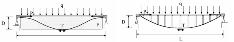
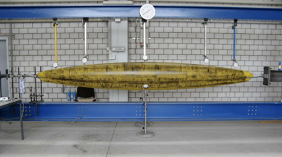
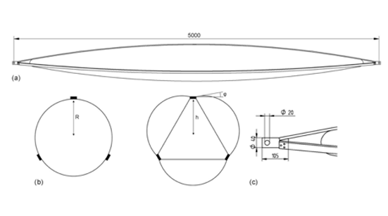
The most basic form of Tensairity beams is based on a cylindrical air beam filled with pressured air, a compression element connected to the air beam and two cables connected at both ends of the compression element and running in helical form around the air beam.

Tensairity girder (left) compared to a truss girder (right). Basically, the vertical struts of the truss are replaced by an airbeam in the Tensairity structure with important consequences.

Other shaped of girders

Preliminary design of spindle shaped Tensairity girders

Spindle shaped Tensairity girders are the results of the further development of the initial Tensairity concept. The main advantage it that, in case of vertical load applied in both directions, they can include two rigid elements placed at the top and at the bottom of the inflated beam which are designed to work alternatively in tension and in compression according to the direction of the applied load.

A spindle shaped Tensairity girder under test at the Center for Synergetic Structures, EMPA, Duebendorf, Switzerland

Preliminary design of Tensairity arches

In order to be a viable solutions Tensairity beams require rigid elevated supports at the two ends which are generally obtained with steel columns or transportable containers or semitrailers. Tensairity arches have the potential of providing  a shelter without the need of additional rigid components which compromise the transportation volumes, the minimal weight and the easy set up.  Despite segmental arches with a reduced rise can be obtained by changing the geometry  of a spindle shape Tensairity beams, such as the 38m span roof designed by Airlight in 2010 for the  National Tennis Center in London, the most successful commercial solutions are based on round arches or horseshoe arches which minimize the waste of floor area.

Dimensions of the Tensairity arch with 10 m span.
Test configuration of the 10 m Tensairity arch.

Preliminary design of Tensairity columns

The design approach to Tensairity columns is described in the work of Wever and includes the results of computer simulations and loading tests carried out to investigate the effect of fabric webs inside the membrane hull on the static response of spindle-shaped Tensairity columns under axial compression. The results confirm  that both axial stiffness and load bearing capacity increase with hull pressure. In addition, the use of fabric webs inside the hull results in a significant improvement of the structural performance of the column.

Experimental configuration for full-scale testing of Tensairity columns subjected to axial compression
Figure X Spindle-shaped columns studied: ( a)front view; (b)midcross sections of plain spindleleftand web spindleright; and (c)cylindrical end par.

Advanced structural simulations

Software

The analytical Tensairity models presented in this document relies on various simplifications and are supposed to provide only a principal understanding of the interactions between cables, compression element and air-beam in Tensairity. For more complex projects or tube shapes, numerical investigations based on appropriate software and algorithms are recommended.

Examples of software successfully used for the advanced structural design of Tensairity® structures includes ANSYS [7] and Abaqus explicit [10]. Due to the combination of interacting cables, compression elements and membranes in Tensairity the FEA requires a non-linear model both in geometry and material.

Example of FEM simulations based on and Abaqus explicit validated through physical tests.